DEFINITION:
Electromagnetic interference (EMI) is any unwanted, induced, electrical voltage and/or current that interferes with the desired ideal electrical signal of a circuit design.
EMI takes on several forms. A good example is the interference one can view on a television screen when a small AC appliance is turned on nearby.
Voltage and current levels are changing at significant rate to cause induced current in other unrelated nearby circuits.
PROBLEMS:
The controls in our industry have to contend with several types of EMI:
- LINE FREQUENCY PICKUP OR AC "HUM"
All interference signals caused by the voltage or current variations in the 60 Hz power line wires are caused HUM. They get this name from the fact that, if the interference is amplified and fed to a loud speaker, the resulting sound is a low hum.
AC HUM rarely damages circuits but rather tends to disturb stable control.
- VOLTAGE TRANSIENTS
Voltage transients or spikes are caused by rapid changes in voltage. Transients are caused by relays, motors, and fluorescent and incandescent lamp loads. Voltage several times the normal voltage level in a circuit can be generated.
- GROUND LOOPS
Since ground loops and ground-loop interference are elusive and little understood entities, they are often blamed for unexpected interference signals.
Ground loops are closed electrical paths in which sections of the path consist of the ground wires of a system and "earth" ground.
Two principle causes of current flow in ground loops are:
- Differences in potential between the points of earth ground to which the system ground terminals are connected. (see figure:1)
- Inductive pickup - due to stray magnetic and radio frequency (rf) fields.
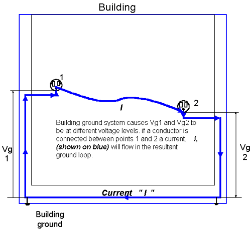
Differences in potential can often exist between two points of a grounding system because the earth and the conductors of a grounding system which are tied to earth ground are not perfect conductors. Since the grounding system of a building carries return currents back to ground, the fact that resistance exists in the wires of the system means that different points along the grounding system can be at different potentials (voltages). Therefore, if a current is flowing in the ground wire, the potential at the point where the ground wire is connected to the wall outlet will not be zero.
SHUNT CAPACITANCE
A capacitance may exist between conductors and when high frequencies (like those that exist when digital information is being transmitted) are present; shunt capacitance causes signal distortion and energy loss.
At high frequencies impedance (resistance) decreases across a capacitor. Therefore current that exist in conductors will take the path of least resistance, across the capacitor causing, a shunt (short) effect. (see figure:2)
Figure 3. |
SOLUTIONS:
While this seems impossible at first, a little foresight BEFORE installation can at least reduce interference. Some recommended wiring practices are:
|
The key to preventing or eliminating ground-loop interference relies on applying special grounding techniques to the entire system. These techniques are based on the fact that current cannot flow in any path unless a complete loop exists. The best way to ensure that no ground-loop paths exist is to design the system so that only one point of it is ever connected to ground. In that way there can be no closed loop through earth ground because there is only on link to ground the entire system.
Always consult the manufacturers' technical information on wiring and terminating shields.
Use shielded cable - some general rules on the use of shielded cable are:
- Use a shielded cable with an insulated jacket such as Belden Belfoil.
- Connect the shield at only one point.
- Any device with more than one cable should have all shields connected to the same physical point.
- The shield should not carry any current. Do not use as a conductor.
- When splicing shielded cable, assure shield is also spliced and insulated.